G.E.R.D. Ltd (German Energy Recovery Design) calls on all international Stake Holders in Shipping: Ship Owners, Ship Managers and Ship Yards. We offer truly low cost solutions to achieve CII (Carbon Intensity Indicator) targets and install both Class approved Systems while vessels are trading. No lay-ups, no delays.

WHRS (Waste Heat Recovery Systems) and MEIER (Marine Electric Injection Equipment Readiness) are both operating automatically and independently of existing ship's automation. Together, WHRS and MEIER can prove to be the only measure required to achieve the CII targets.

We do guarantee, that our combined systems achieve annual fuel saving of 650 to 750 MT, which equates to about 2.75 MT/day for 254 days of annual ME (Main Engine) operation. We question seriously, that further ME derating is able to achieve that. But, more importantly, we are certain, that the combined cost of WHRS and MEIER is a mere fraction of the cost for any ME derating.

The warranties for WHRS and MEIER are confidently set to 3 years from date of installation, following successful long term endurance tests.

WHRS Technology

AV 250 AV 125 AV 50

Interlock for ME CW Pump

WHRS Power Pack

The simplicity of WHRS design resulted in Low Cost Production and great reliability, proven by endurance tests of 10,000 operating cycles in 2018. This equals more than twelve years onboard operation.

This success prompted G.E.R.D. Ltd to attach a three year warranty to all WHRS Actuator- Valves (AVs).

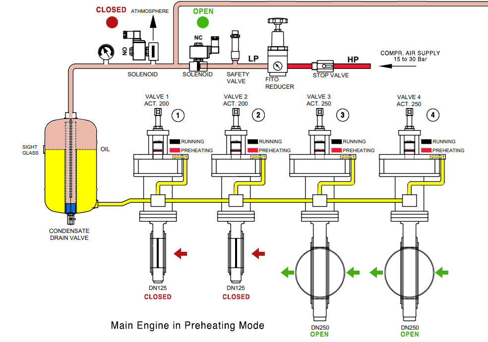
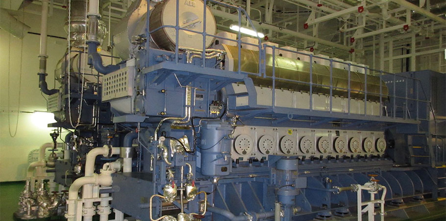
WHRS uses generator waste heat contained in the cooling water and directs it automatically to all standby generators and Main Engine (ME).

Generator electric preheating and ME steam heating remain in place, but are redundant when WHRS is retrofitted. Ship Yards install universally capacities of 1.5 % of MCR (Maximum Continuous Rating) on all preheat systems for both, electric and steam heating.

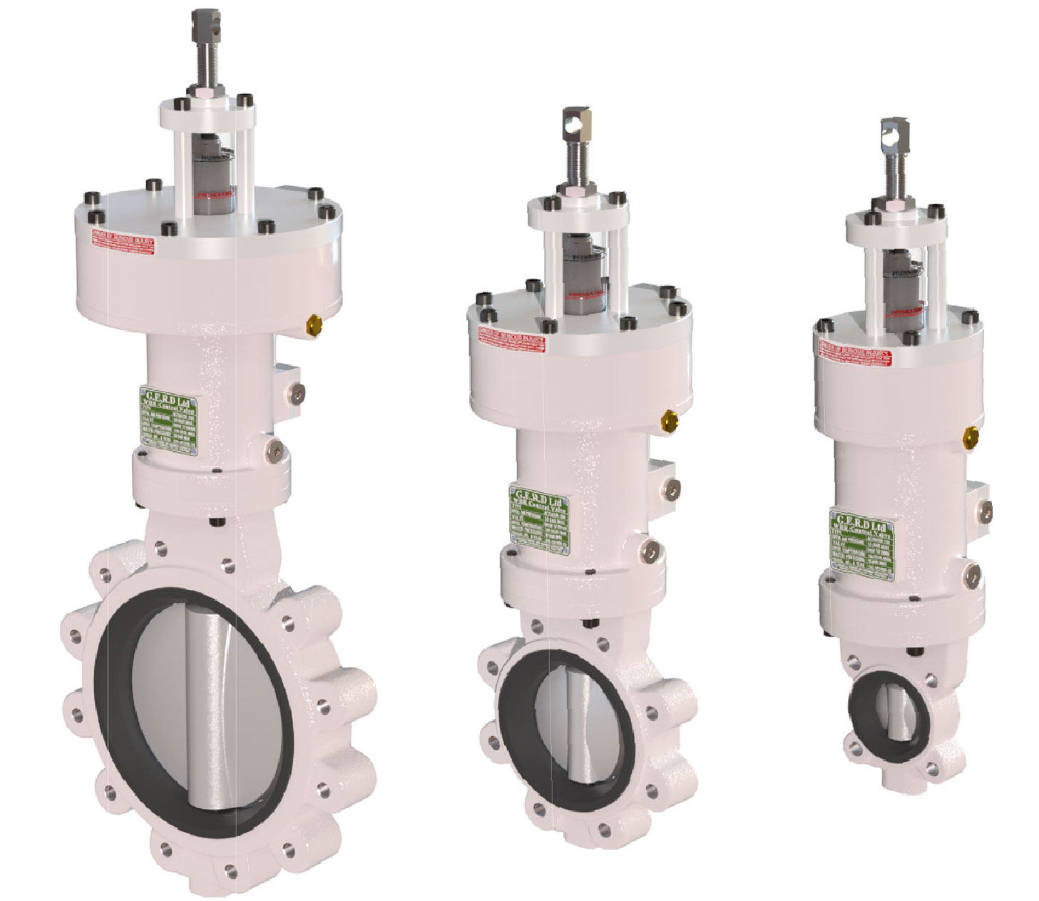
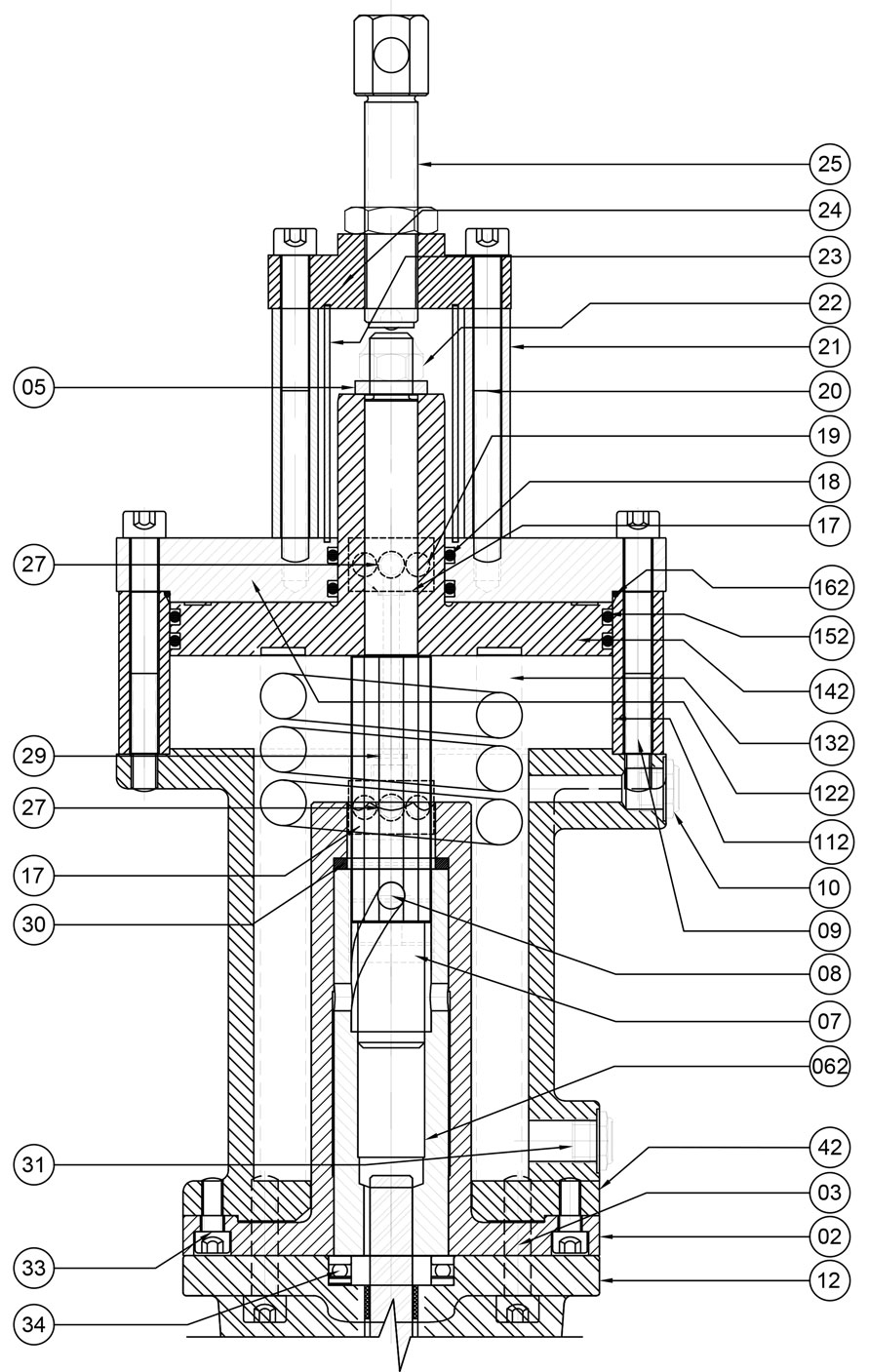
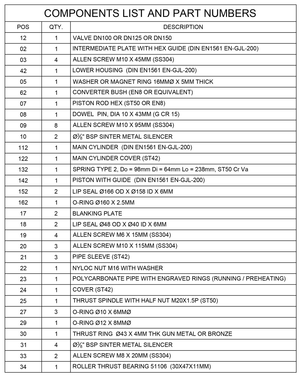
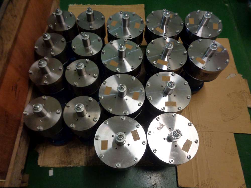
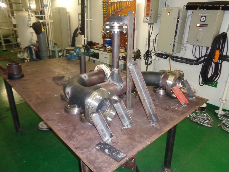
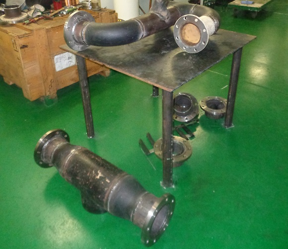
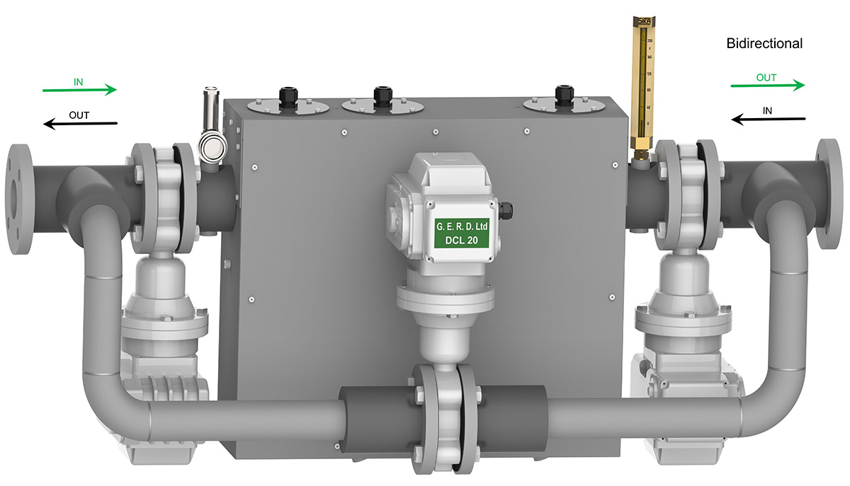
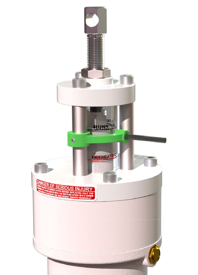
The automatic diversion of preheating water is facilitated by modified butterfly valves, operated by specially designed Actuators, available in three different sizes.

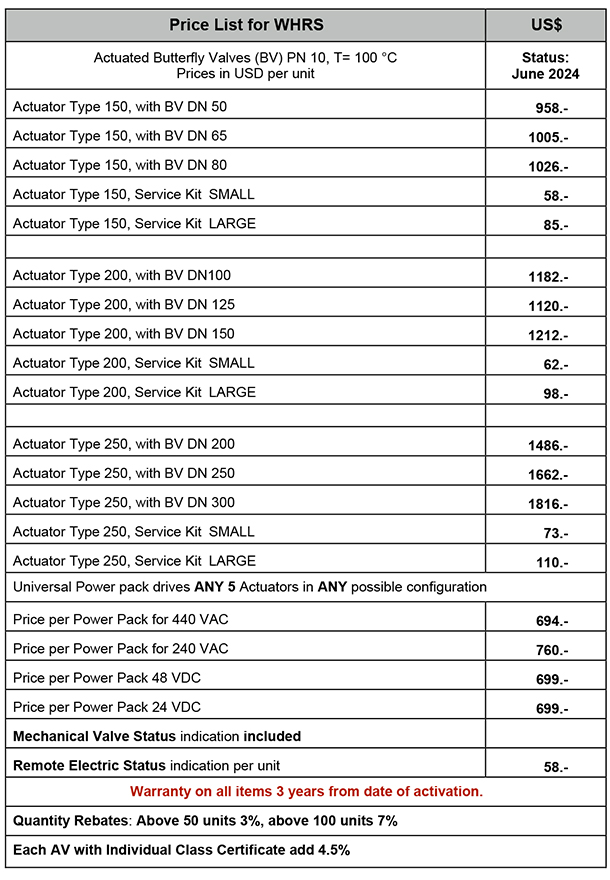
They are capable of operating all valves from DN50 to DN300.
All flange types, such as DIN, JIS and ANSI are available
on request and at no additional cost.

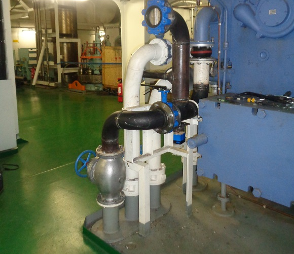
Whenever a generator is started, it becomes automatically a contributor of waste heat, delivering hot cooling water into a Ring Main. Upon stopping, WHRS turns the same engine into a recipient of waste heat.

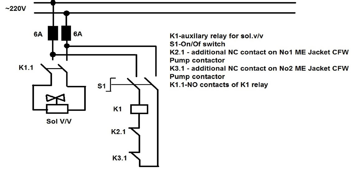
The Main Engine preheating is triggered by an ON/OFF switch in the control room.

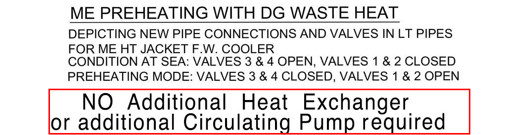
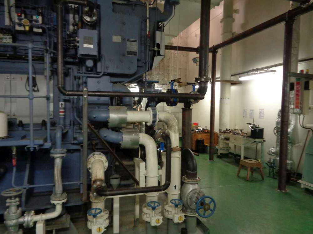
The Main Engine HT (High Temperature) cooling water pump is not required for this process, which constitutes a further fuel saving during preheating, averaging 0.25 MT/day.

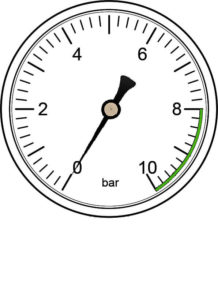
Circulation is affected solely by the DG (Diesel Generator)  attached CW (Cooling Water) Pumps (typical Q = 90 to 100 qbm/h  and  P = 4 to 5 bar).

The ON / Off switch/relay usually serves also as an electric interlock for the circulating pump.

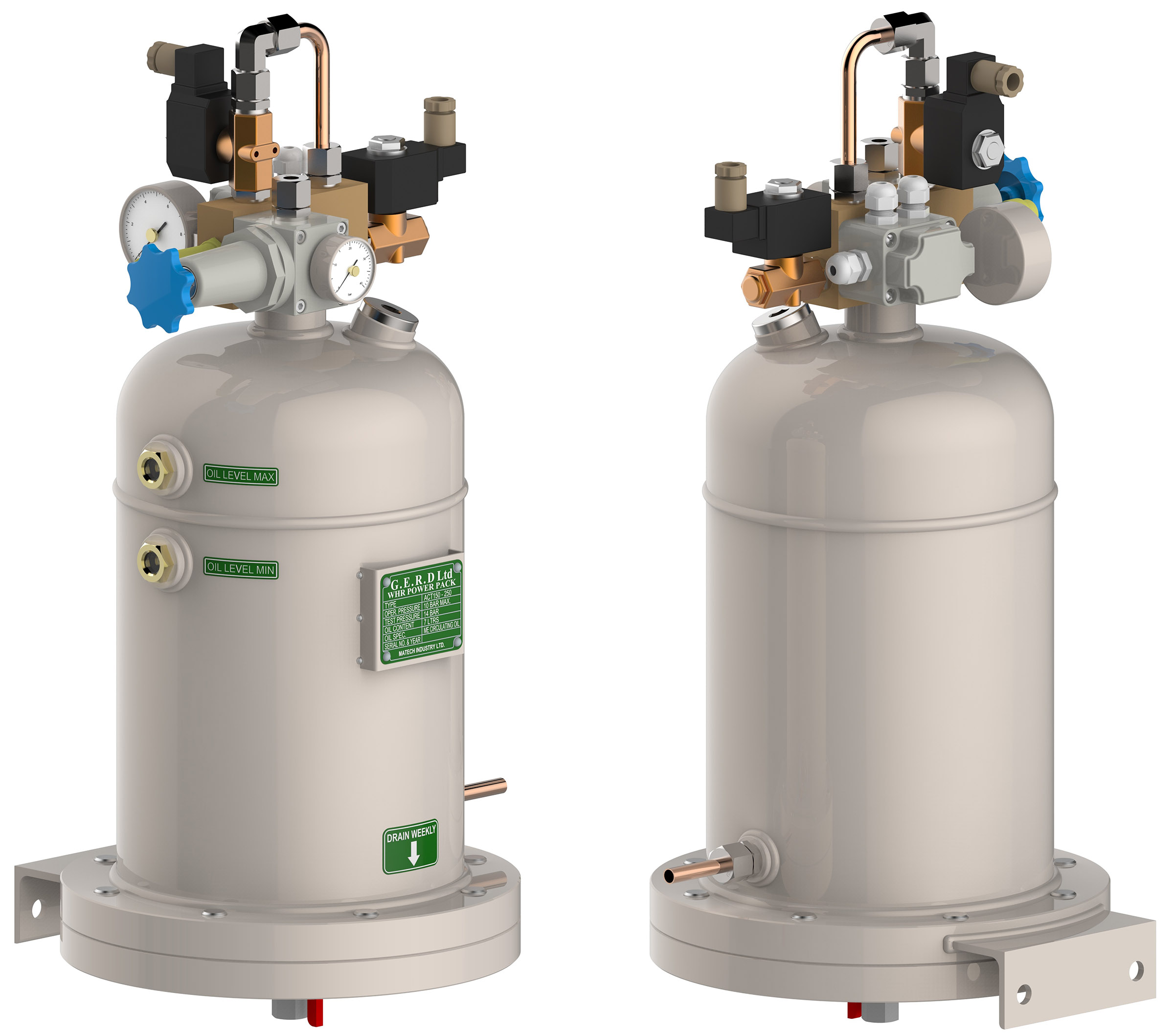
G.E.R.D. Ltd uses individual Power Packs (PP), to drive WHRS, each capable of operating up to six Actuator-Valves (AVs) of unlimited size. Although our Actuators can operate with DG Engine oil pressure on request, we strongly recommend to choose the Power Pack version at all times.

The advantages for choosing Power Pack operation range from guaranteed reliability and justified safety concerns to unlimited choice of valve size.

Without Power Pack operation, G.E.R.D. Ltd has to reduce the  warranty for Actuators from three years to one year.

PP operation affords also unlimited operating power adjustment.

For automatic operation, WHRS requires one Power Pack for each Generator and one for the Main Engine.

WHRS Actuator Functions

Actuator Internal Oil Passage

The Power Pack tank holds 8 Liters of ME circulating oil, two sight glasses provide oil level control.

The oil is pressurized by compressed air, which is released automatically upon engine stop by solenoid valves.

Please refer to section WHRS Animated Function Diagram.

WHRS for generators is triggered by the Start/Stop signal of the respective Luboil Stand By Pump. The solenoid valves for WHRS for Main Engine are activated by ON/OFF switch in the control room.

See diagram in section WHRS Technology.

Actuator Maintenance

The Actuator maintenance requirements are laid down in the Technical Handbook. In short, ONLY every four years, the Actuators should be dismantled, inspected and all O-Rings and Lip Seals be changed. At this point the grease filling should be renewed with
MOBIL Grease XHP 220 or equivalent. Likewise, Oil in the Power Pack must be changed.

G.E.R.D. Ltd provides complete maintenance kits which include all O-Rings, lip seals, dowel pin, thrust bearing and thrust ring and replacement silencers (all included in G.E.R.D. Ltd SMALL Maintenance Kit).

The Main Springs should be exchanged after 8 years of Service
(they are included in G.E.R.D. Ltd  LARGE Maintenance Kit).
Special Long Life Hydraulic Seals are under development. 
Once available, maintenance intervals may be further extended.
We will keep all our customers posted.

The pressurized oil enters the Actuator at any one of the 4 entry ports at the oil connection point (see above Actuator Internal Oil Passage). As the drawing shows, the fluid travels through a 6 mm bore inside the wall of the Main Cylinder (part 112) sealed by O-Rings (parts 27&29). Further sealed by Blanking Plate (part 17), it enters the bore in the Main Cylinder Cover (part 122) from where it follows the ring shaped groove on top side of Piston with guide (part 142).

The pressurized oil moves the piston and Piston Rod (Part 07) downwards, where the Dowel Pin (Part 08), engaged with the Converter Bush (part 62) converts the vertical motion of the dowel Pin into a rotation of 90 degrees. The lower end of the Converter Bush rotates freely on the Roller Thrust Bearing
(Part 34) and is engaged with the spindle of the Valve (Part 12) moving it from OPEN to CLOSED position and vice versa.

During the downward motion of the piston the Main Spring (part 132) is being compressed, storing the energy for the return stroke of the piston upon change from Preheating to Running when the generator is started. At this point, the solenoid valve closes the driving air inlet and opens the vent solenoid valve to atmosphere. See also WHRS Animated Function Diagram on this website.

WHRS Animated Function Diagram

OPERATING
AIR PRESSURE

ME

PREHEATING

Legend

WHRS at New Building versus Retrofitting

Typical DG installation on ships prior to conversion with WHRS

It will be obvious, that installation of WHRS at New Building stage has major technical and financial advantages. It should be impossible to even contemplate the planning of engine plants for new vessels without considering WHRS for various reasons:

  • At New Building Stage, the return on investment (ROI) for Owners and Operators is achieved inside 8 weeks by direct fuel savings alone, which results in considerable, subsequent reduction of GHGE (Greenhouse Gas Emission).
  • The latter will greatly assist, to achieve with ease the mandatory EEDI (Energy Efficiency Design Index) stipulations, as adopted by MEPC 62 (Marine Environment Protection Committee) in July 2011 for new vessels.

Assembled Actuators, pre installation

Ship Owners might struggle with existing ships to reach the mandatory IMO (International Maritime Organization) Targets of CII (Carbon Intensity Indicator) and EEXI due to be enforced in January 2023.

G.E.R.D. Ltd has plenty of first hand experience in retrofitting WHRS whilst vessels are trading. For sister ships, we have adopted prefabrication programs which reduce fitting time on board very considerably.
Never have we caused even a single hour delay on board during WHRS conversion work.
The general rule of thumb is, that retrofitting WHRS is about 30 to 35% more expensive compared with cost at New Building Stage .
Consult with us further through g.e.r.d.ltd@fuelsavers.org

Fabrication on board

Further Fabrication on board

Advanced new pipe work

Completed new pipe work

WHRS Fuel Saving and GHGE Reductions

Average daily fuel saving through WHRS for ME preheating in port: 3.84 MT/day

WHRS and MEIER are both very effective fuel saving measures and reduce GHGE very considerably. 

Fuel Consumption (MT) x Factor 3.11 = CO2 Emissions (MT)

The overriding aim has been to reduce the very inefficient OFB (Oil Fired Boiler) operation, substituting preheat requirements with WHRS and eliminate the OFB operation in port altogether through MEIER. (Keep Main Steam Valve closed.)

Statistical data was extracted from 43 vessels owned by HSDG, indicating average annual port stay or anchorage of 104 days.

During these periods the ME was steam heated with capacity of
1.5 % of MCR and DGs electrically with 35 kW each for 365 days/year.

G.E.R.D. Ltd converted four vessels of HSDG with WHRS and supplied components for a further six ships.

The average observation period after installation was five months.
All vessels had at least four generators, some had five.

Log abstracts indicated, that electric preheating for generators was used on average for 2.3 generators per vessel and day during each calendar year. 
With WHRS preheating ME, FW (Fresh Water) Pump is not running.

Here are the results:

WHRS saving for ME preheat, 104 days x 3,84=399.4 MT/year
Saving from FW Pump 104 days, 35 kW Motor=21.8 MT/ year
2.3 generators each 35 kW el. heater,  365 days=176.3 MT/year
Saving through MEIER 104 days x (1.44 – 0,21)=127.9 MT/year
Total saving per vessel and year=725.4 MT/year

Reduction of fuel cost (@ USD 820/MT) USD 549,828 /year.
Reduction of CO2 emission per vessel 2,255 MT/year.

Average Temperatures achieved on 4 sample vessels with ONE Generator contributing at 870 kW Load:
Generators: 77/ 78 centigrades, Main Engine: 75/76 centigrades (Max ER (Engine Room) Ventilation).

MEIER® Marine Electric Injection Equipment Readiness

MEIER Heater Type MEHL 9 in DN50 (2")

Standard MEIER heater MEH 20

For maximum efficiency, MEIER should always work in conjunction with WHRS. Once both are installed, OFB operation in port will be eliminated .

The standardized MEIER-units can be supplied in capacities from 6 kW to 24 kW and multiples thereof. The type designation is always MEH followed by the capacity indication, ranging from 6 -9-12 etc to 60 kW.

The capacity of MEH 18 is sufficient, to heat daily DG fuel consumption of 10 MT in 24 hrs from 60 to 140 °C AND take care of all required heating for injection equipment of ME and stopped DGs.

All MEIER Units can be delivered with automated change over valve from steam operation to electric heating. Change over will ONLY take place, when the preset temperatures of the MEIER System have been reached.

MEIER will serve numerous purposes: With Main Steam Valve at OFB closed and the boiler on stand by under mean operating pressure, MEIER is designed to:

  1. Substitute all Steam Heating Requirements in Port, making OFB operation redundant. 
  2. Heat and maintain the desirable fuel oil temperature for unlimited Generator Fuel Consumption in port.
  3. Maintain the required injection Equipment Temperature of all other Generators and Main Engine.
  4. Standard MEIER equipment Type MEH 18 is capable to heat generator fuel consumption of 10 tons per day with a design temperature differential of 80 °C.
  1. Outlet Fuel Temperatures can be set from 60 to 140 °C at the MEIER Control Panel with digital displays, including “auto cut out” to prevent accidental overheating. NO resets required. All MEIER units regulate accurately to within 2 °C of set temperatures at all times.
  2. Larger MEIER units of 30 to 60 kW are available for exceptional circumstances.
  3. If luboil purification in port is required, it can be easily facilitated by an additional MEIER unit, with reduced heating capacity. This will hardly alter the Fuel Saving Advantage.

Fact is, that Boiler fuel consumption in port, at anchor and in low load conditions is higher by huge margins compared with MEIER energy requirements. This is due to the inherent and atrocious inefficiency of all boilers in low steam output conditions. 

This was irrevocably ascertained from data analysis of 43 vessels with average daily OFB consumption of 3.7 MT VLSFO (Very Low Sulphur Fuel Oil) whilst in port and operating under strict fuel saving conditions as laid down in SEEMPs (Ship Energy Efficiency Management Plans).

Numerous tests have proven again and again, that ALL OFBs burn only 80 to 100 kg VLSFO/24 hrs when kept on automatic standby under pressure with main steam outlet-valve closed.

The advantages of MEIER are obvious and best demonstrated in the following diagram, which indicates daily fuelsaving during port stays and at anchor, with combined WHRS and MEIER operation compared with OFB operation.

WHRS : Prices, Warranties and Order Forms

All Valve Flange Connections are drilled and tapped to DIN, JIS or ANSI Standard at no extra cost.

For ordering, general inquiries and technical assistence, please feel free to consult with us and contact us 24/7 by email:
g.e.r.d.ltd@fuelsavers.org or drghelmers@gmail.com

Remote
Status Indication

Payment Terms : 

  • 50 % upon written acceptance of order by G.E.R.D. Ltd which coincides with commencement of production, 50 % prior to dispatch of goods.
  • Payment: via TT or irrevocable LC (other terms by negotiated agreement).
  • Delivery: 60 days from our acceptance of order. FOB terms.

Contact Us

Our Location and Contacts at NOVA Group

Address:         22/F, 3 Lockhart Road, Lockhart Rd, Wan Chai, Hongkong
Sales: g.e.r.d.ltd@fuelsavers.org          Phone +852 9845 6757
Technical: drghelmers@fuelsavers.org          Phone +852 9444 8476  or  +63 906 239 5997

© G.E.R.D. Ltd ® (German Energy Recovery Design) 2024